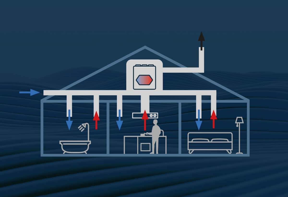
Modbus RTU and Modbus TCP enable air handling units to be integrated into a building automation system (BAS), allowing their operation to be monitored and controlled centrally. For example, the system can retrieve temperature readings, operating status information and alarm data from air handling units in an apartment building.
The main difference between Modbus RTU and Modbus TCP lies in how data is transmitted. Modbus RTU typically uses an RS-485 serial bus, while Modbus TCP communicates over TCP/IP, usually through an Ethernet network.
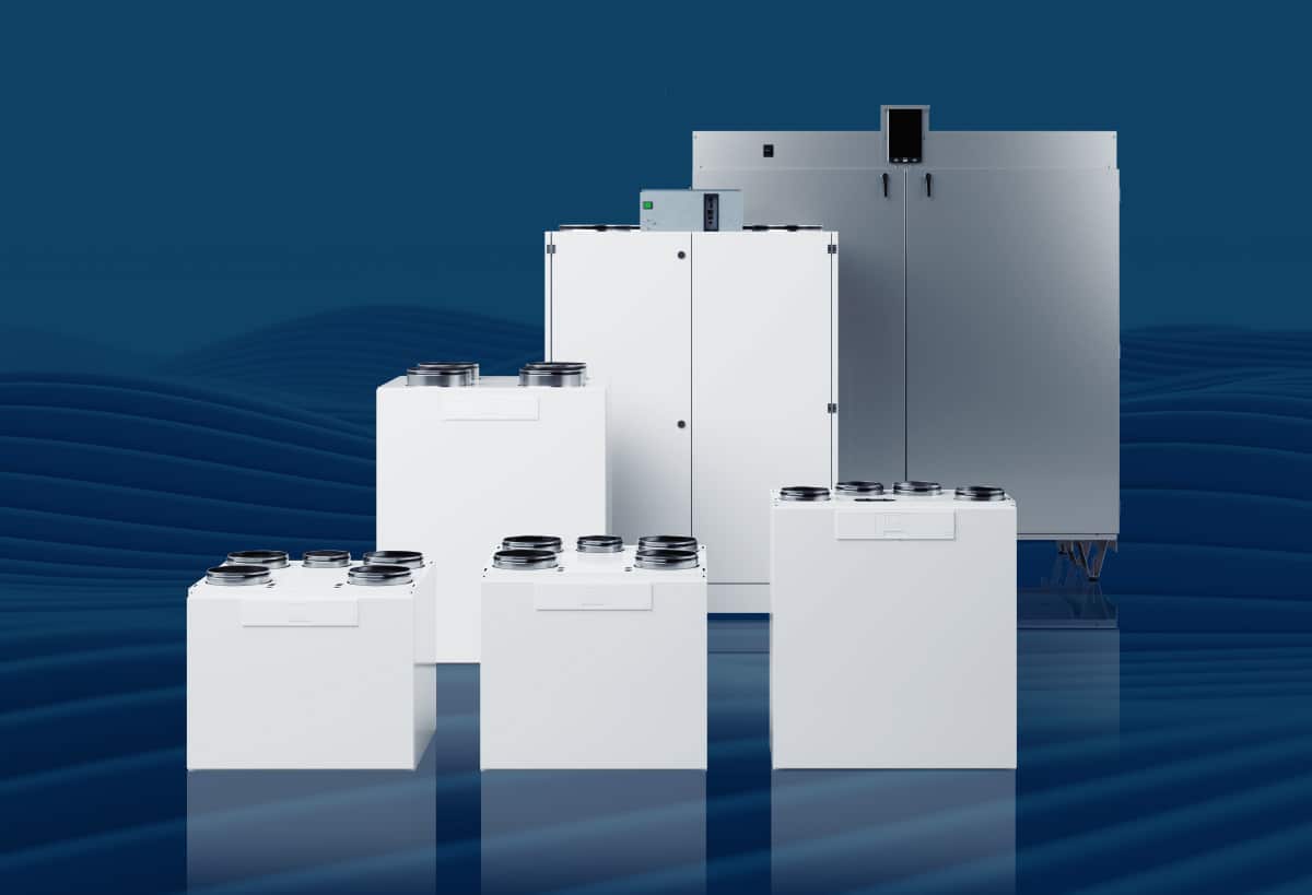
When choosing between the two protocols, the key considerations are the interfaces supported by the equipment and the building’s communication network. Airfi air handling units come with both Modbus RTU and Modbus TCP interfaces as standard, and both can also be used simultaneously.
Modbus RTU and Modbus TCP: Differences in Building Automation for Ventilation Systems
| Feature | Modbus RTU | Modbus TCP |
| Interface | Typically RS-485 | Ethernet |
| Cabling | Typically, twisted-pair cable | Ethernet cable (Cat6 or newer) |
| Speed | Typically 9 600–11 5200 bps | Typically 100 Mbps or 1 Gbps |
| Device addressing | Slave ID (1-247) | IP address and Unit ID if required |
| Port | Serial port | TCP port 502 |
| Topology | Serial bus / bus topology | Ethernet network, star or tree topology |
| Data transmission verification | CRC16 | TCP and Ethernet error checking |
| Multiple connections | One query at a time on the bus | Multiple TCP connections are possible |
| Application | Field Devices and Meters | PLCs, control rooms, and network-connected devices |
The connection method, or network topology, of a Modbus network depends on the communication technology used. In a Modbus RTU RS-485 network, devices are typically connected in a daisy-chain configuration along the same bus. In a Modbus TCP Ethernet network, devices can be connected through network switches in a star or tree topology.
The key difference is how cables are routed between devices. Correct wiring topology is particularly important in Modbus RTU RS-485 networks, as an unsuitable configuration can cause communication problems.
Modbus RTU – Serial Bus
- All devices share the same bus
- Each device has its own Modbus ID
- Master asks for information one piece at a time
- All devices on the bus must have compatible serial communication settings (baud rate, parity, stop bits).
For example, building automation reads data such as temperature, fan speed, and alarm information from the air handling units in an apartment building via the Modbus RTU bus.

Modbus RTU Daisy-Chain Wiring and Bus Topology
Recommended Connection Method for a Modbus RTU / RS-485 Network
- Building Automation > Airfi air handling unit 1 > Airfi air handling unit 2 > Airfi air handling unit 3
- Each air handling unit has its own Modbus ID
- The air handling units are connected in a daisy-chain configuration to the same RS-485 bus
- If necessary, a 120 Ω termination resistor is installed at both ends of the bus to reduce signal interference and improve the reliability of data transmission
- Long branches from the main bus should be avoided, as they can cause signal reflections and communication errors. A daisy-chain connection is recommended.
* In the figure: PLC = programmable logic controller on an Ethernet network. VAK = monitoring sub-center.
Example: Building automation systems can read data from Airfi air handling units via the Modbus RTU bus and send control commands to them.
Restrictions on Star Connections and Splits in the RS-485 Bus
- A standard passive star connection is generally not recommended
- Branches can cause signal reflections
- This can result in occasional connection drops and CRC errors
- A star-shaped network can be implemented using an active RS-485 hub or repeaters
Note: An RS-485 repeater may be required on a case-by-case basis.
Modbus RTU: Passive branches should be avoided; different branches can be implemented using active RS-485 repeaters.
Modbus TCP – Ethernet Network
- The devices are connected to the Ethernet network
- The devices are identified by their IP addresses. Each air handling unit is assigned its own IP address on the network, which allows the building automation system to connect to the correct unit
- Data transfer uses the TCP/IP protocol
- Typically, the Modbus TCP server listens on port 502
Example: A building automation system reads and controls the air handling units in an apartment building via an Ethernet network based on their IP addresses.
Modbus TCP Star Topology
All devices are individually wired to a single central point.
- A star topology is the standard and recommended method
- Devices are connected to an Ethernet switch
- Each device has its own network cable connected to the switch
Example: Each air handling unit is connected via its own Ethernet cable to a central point, such as an Ethernet switch. Through the switch, the ventilation units are connected to the same network, and the building automation system can communicate with them.

Tree Topology of a Modbus TCP Network
In a tree topology, the network branches into several parts.
- Modbus TCP: can be easily implemented using multiple Ethernet switches

Can Modbus RTU and Modbus TCP devices be used in the same system?
Yes. A Modbus TCP–RTU gateway enables data transfer between a system on an Ethernet network and devices connected to an RS-485 bus. The gateway bridges the communication protocols, but the devices’ register data is still required to implement the integration.
Which is better for building automation of air handling units: Modbus RTU or Modbus TCP?
Airfi air handling units support both Modbus RTU and Modbus TCP communication, including simultaneous operation. This means that the same air handling unit can communicate via Modbus RTU over an RS-485 bus and via Modbus TCP over an Ethernet network. Depending on the building automation solution, either connection method can be used individually, or both can operate in parallel.
Modbus RTU is suitable for installations where field devices have an RS-485 interface and the goal is a cost-effective bus solution. A shared bus must also be taken into account during troubleshooting: a problem with the bus cabling or data transmission can affect the connection of multiple devices.
Modbus TCP is suitable for installations where air handling units have Ethernet interfaces and the aim is to use an existing IP network or establish connections to multiple systems. Each air handling unit is identified on the network by its own IP address. For example, an apartment building’s network can be implemented using Ethernet switches on individual floors.
Airfi’s Modbus Register List to Support Integration
Airfis Modbus Register List helps with the implementation and maintenance of building automation integration. The list is expanded with registers required for new features without changing previously published register definitions. The numbering in the register list starts at one, so during integration, you must verify how the building automation system you are using represents register addresses and how they correspond to the numbering in the list.
Using a Modbus TCP–RTU gateway, for example, a programmable logic controller (PLC) on an Ethernet network, for example, can read data from ventilation units connected to an RS-485 bus that use the Modbus RTU protocol. We welcome customer suggestions for enhancements to the Modbus register list and are happy to assist with any integration-related questions.
Are you planning to integrate Airfi units into a building automation system?
Airfi air handling units come standard with both Modbus RTU and Modbus TCP interfaces, so you can choose between an RS-485 bus, an Ethernet network, or both in parallel for your project. If you’re wondering which option is best for your project or how the register list numbering corresponds to the addresses in your system, please contact us. We’ll help you with the planning and implementation of the integration.